Spectrum Domain Nodes
1 Brikwall Filter
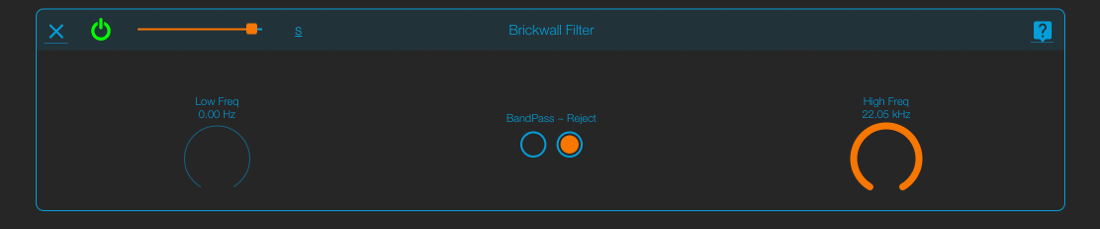
A spectral brickwall filter.
Low Freq: the components below this parameter are filtered out.
High Freq: the components above this parameter are filtered out.
Bandpass/Reject Switch: when in reject mode the brickwall filter filters out the frequencies inside the two frequency parameters.
Low Freq: the components below this parameter are filtered out.
High Freq: the components above this parameter are filtered out.
Bandpass/Reject Switch: when in reject mode the brickwall filter filters out the frequencies inside the two frequency parameters.
2 Spectrum Runner
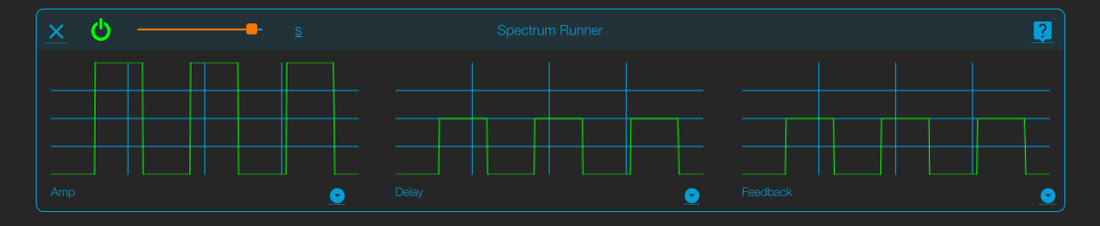
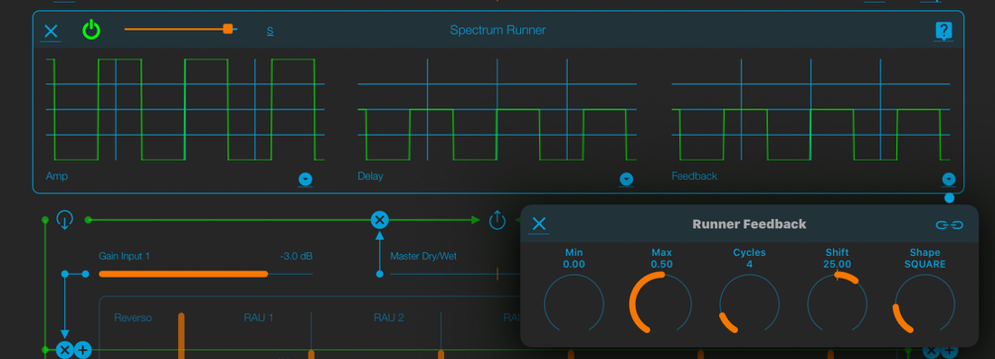
A spectral delay with feedback
This node has three “spectral LFOs” to modulate the amplitude, the delay and the feedback of the spectral components
The edit window shows three oscilloscopes, one for each spectral LFO A little circular icon on the bottom right of the oscilloscopes open the parameter window
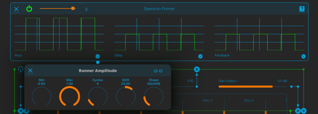
Amplitude Parameters"
Min" sets the minimum amplitude (the minimum LFO value)
Max" sets the maximum amplitude (the maximum LFO value)
Cycles: how many cycles of the spectral LFO are generated in the spectrum space
Shift: when this parameter is not equal to 0 the LFO scrolls in the spectrum space, generating dynamic variation in the components
Shape: the waveform of the LFO- Sine, Square, Triangle, Ramp Up, Ramp Down, Pulse
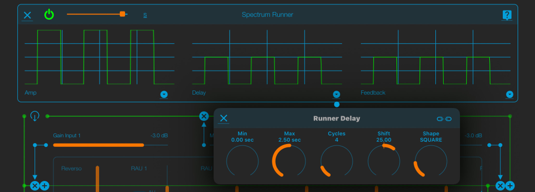
Delay Parameters-
Same as the Amplitude Parameters, except Min and Max which are expressed in seconds
Feedback Parameters"
Same as the Amplitude Parameters
This node has three “spectral LFOs” to modulate the amplitude, the delay and the feedback of the spectral components
The edit window shows three oscilloscopes, one for each spectral LFO A little circular icon on the bottom right of the oscilloscopes open the parameter window
Amplitude Parameters"
Min" sets the minimum amplitude (the minimum LFO value)
Max" sets the maximum amplitude (the maximum LFO value)
Cycles: how many cycles of the spectral LFO are generated in the spectrum space
Shift: when this parameter is not equal to 0 the LFO scrolls in the spectrum space, generating dynamic variation in the components
Shape: the waveform of the LFO- Sine, Square, Triangle, Ramp Up, Ramp Down, Pulse
Delay Parameters-
Same as the Amplitude Parameters, except Min and Max which are expressed in seconds
Feedback Parameters"
Same as the Amplitude Parameters
3 Grip
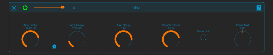
This node samples and holds spectral components of the incoming signal, based on their amplitude
Amp Center: This is the center of the held spectral components amplitude range; all components whose amplitude falls in this range are held
Amp Range: The amplitude range width
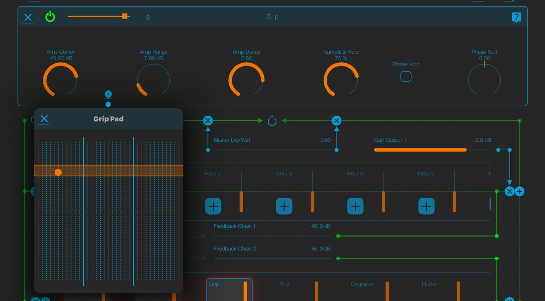
You can edit graphically the two parameters above by tapping the small circular icon between the two knobs
Amp Decay: Amplitude decay for the held components" it ranges from 0 (shortest) to 1 (longest)
Sample & Hold: the percentage of components held (when they are included in the Amp Range)
Phase Hold- this switch freezes the components phase‘ the result is a drone resonance, whose frequency depends on the sample rate
Phase Mult- multiplies the freezed phases value
Amp Center: This is the center of the held spectral components amplitude range; all components whose amplitude falls in this range are held
Amp Range: The amplitude range width
You can edit graphically the two parameters above by tapping the small circular icon between the two knobs
Amp Decay: Amplitude decay for the held components" it ranges from 0 (shortest) to 1 (longest)
Sample & Hold: the percentage of components held (when they are included in the Amp Range)
Phase Hold- this switch freezes the components phase‘ the result is a drone resonance, whose frequency depends on the sample rate
Phase Mult- multiplies the freezed phases value
4 Blur
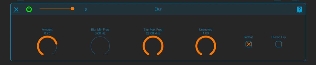
A (noisy) “spectral reverb” The duration of the spectral components are prolonged (blurred)
Amount: length of the blurring When this parameter is 1 the spectrum is frozen
Blur Min Freq: the minimum frequency to be blurred
Blur Max Freq: the maximum frequency to be blurred
Unblurred: the amplitude of the non-blurred components (those outside the Min-Max range above)
In/Out: when toggled the blurred components are those outside the Min-Max range
Stereo Flip' Blurs the entire spectrum; the components inside the Min-Max range are on the left channel, those outside are on the right channel The behaviour is reversed if the In/Out switch is on
5 Degrader
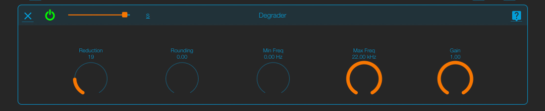
A spectral decimator
Reduction: a division factor for the spectral components lf, for instance, the components are 512 and the Reduction parameter is 4, the components become 512/4 = 128
Rounding: generally the amplitude of a single component goes from O to number-of-components (i e if we have 512 components, the amplitude of a single component can range from 0 to 512) The rounding factor sets the value of a single step in amplitude If it is 0 you have all possible values, if it is 1 you only have integer values, if it is 2 you only have even values, if it is 3 you only have multiple of 3 and so on
Min Freq: minimum frequency affected
Max Freq: maximum frequency affected
Gain: sets the gain of the decimated signal
6 Flutter
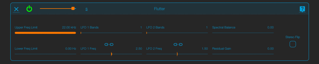
Flutter is a sort of animated brickwall Two spectral sinusoidal LFOs define the frequency boundaries The spectral components which are inside or outside (depending on the Spectral Balance) these boundaries are suppressed
Upper Freq Limit and Lower Freq Limit: the effect takes place only inside these limits
LFO 1 Bands: in how many cycles the first LFO covers the signal spectrum
LFO 1 Freq- at what the rate the first LFO slides along the signal spectrum
LFO 2 Bands: in how many cycles the second LFO covers the signal spectrum
LFO 2 Freq- at what the rate the second LFO slides along the signal spectrum
Spectral Balance: when this parameter is O the spectral components which are inside these boundaries are suppressed; when it is 1 the spectral components which are outside these boundaries are suppressed.
Residual Gain: this is the gain of the frequencies not processed, i.e. the frequencies not included in the band between the Upper Freq Limit and Lower Freq Limit.
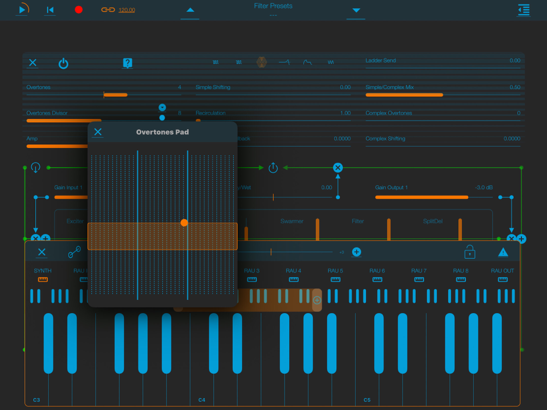
The monophonic Synthesizer
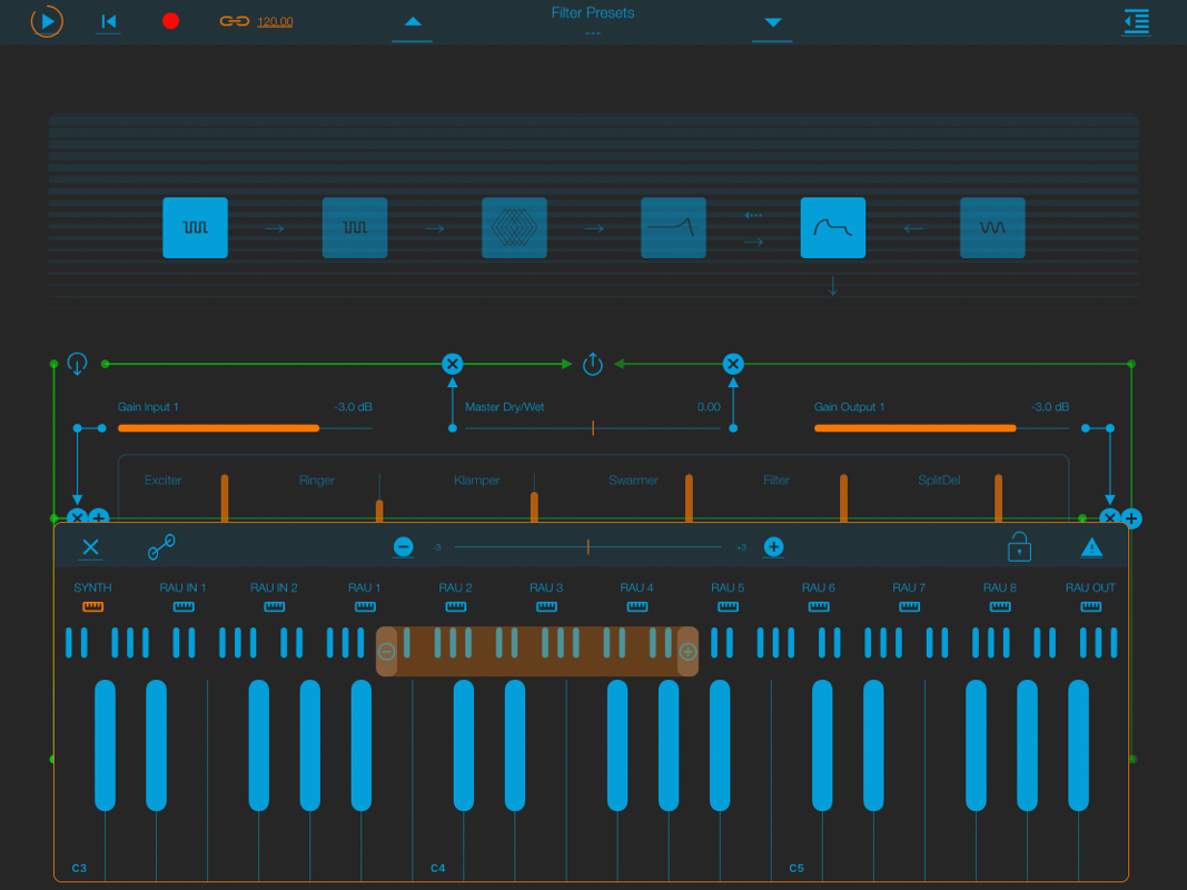
You can use the internal monophonic synth as a source by choosing it in the Input Selection Window.
The synth contains two band limited oscillators (1 and 2), a complex oscillator (3), a ladder filter (4), an envelope generator (5) and a sub- bass oscillator.
Tap on one of the six icons to open the relative edit window. Inside an edit window you can navigate to the other windows using 6 little icons on the top.
Each component of the synth, apart from the envelope generator, can be switched on and oh‘ by tapping the “power” icon in the upper left of each edit window.
1 & 2 Band Limited Oscillator
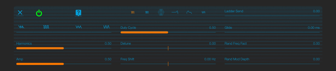
The band limiter oscillators have a generator capable of morphing between the four classic waveforms: sawtooth, square, triangle and sine. They also contain a noise modulator.
Waveform: use this parameter to morph between the different waveforms.
Tap on the small icons above the fader to precisely select one of the four waveforms.
Harmonics: this parameter sets the quantity of harmonics of the waveform i e its brilliance
Amp: the amplitude of the oscillator
Duty Cycle: ratio between the first and the second half cycle in the square and triangular waveforms
Detune: pitch transposition in semitones
Freq Shift: adds or subtracts a fixed amount of hertz to the pitch
Ladder Send: the amount of signal sent to the Ladder Filter
Glide: pitch portamento between notes in milliseconds
Rand Freq Fact: multiplication factor for the frequencyfthe random modulator
Rand Mod Depth" depth of the random modulation
3 Complex Oscillator
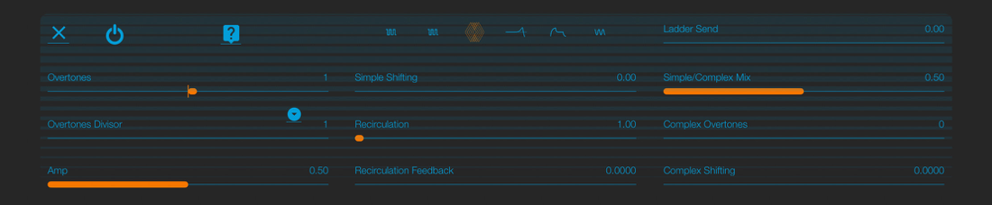
The complex oscillator uses a new synthesis technique we called “Split Synthesis”: it is based on difierent processing of the positive and negative parts of the waveform.
Overtones: this parameter emphasizes the overtones of the oscillator using a frequency shifter Negative numbers are not “undertones” but overtones obtained using negative frequency shifting (try it to hear the difference)
Overtones Divisor: the frequency shifting set with the first parameter is divided by this one This creates undertones and/or inharmonic components
Amp: the amplitude of the oscillator
Simple $hifting- this is an additional frequency shifting which increases the overtones frequency shifting above, creating beatings and inharmonicities
Recirculation: a delay line with feedback is included in this oscillator The
Recirculation parameter sets the number of delay repetitions per cycle
Recirculation Feedback" this is the feedback parameter for the delay line If
it is set to O, the recirculation has no effect Values above 1 generates heavy
distortion
Ladder Send: the amount of signal sent to the Ladder Filter
Simple/Complex Mix- there are two split synthesis modules in cascade' the output of the first is the “simple” one, the second is “complex” With this parameter you can mix the two outputs
Complex Overtones: with this parameter you can shift the frequency of the second module If the Simple/Complex Mix parameter above is 0, this parameter has no effect
Complex Shifting: this is an additional frequency shifting which increases the Complex Overtones frequency shifting above, creating beatings and inharmonicities
4 Ladder Filter
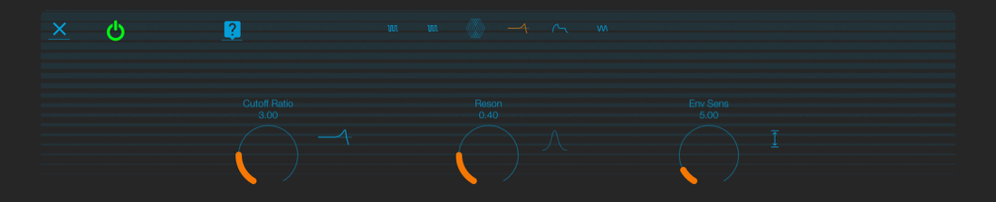
A high quality anti-aliased analog emulated Ladder filter Cutoff Ratio: the cut-off frequency as a ratio of the note frequency; f i if the note frequency is 220 Hz and the Cutoff Ratio is 3, the actual cut-off frequency will be 660 Hz (22Ox3)
Fleson: resonance factor When it is 1 or more the filter resonates by itself, even with no signal in input
Env Sens: envelope sensitivity‘ the amount of cut-off frequency influenced by the envelope For example, if the Cutoff Ratio is 3 and the Env Sens is 2, the actual cut-off ratio goes from 3 to 5 and back to 3 following the amplitude
envelope shape
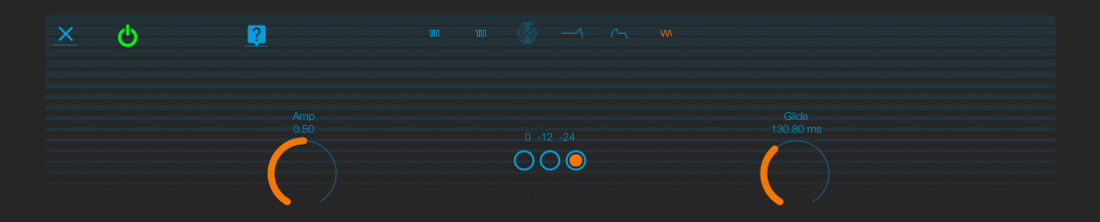
5 Sub Bass Oscillator
A sinusoidal oscillator which can be used to reinforce the fundamental of the sound, or to add a sub-bass component one or two octaves below the
fundamental frequency.
Amp: the amplitude of the oscillator. 0/-12/-24 Switch: the transposition of the oscillator frequency in semitones
(no transposition, 1 octave below, 2 octaves below).
Glide: pitch portamento between notes in milliseconds.
fundamental frequency.
Amp: the amplitude of the oscillator. 0/-12/-24 Switch: the transposition of the oscillator frequency in semitones
(no transposition, 1 octave below, 2 octaves below).
Glide: pitch portamento between notes in milliseconds.
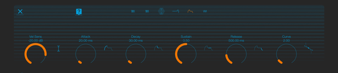
6 Envelope Generator
The classic ADSR envelope.
Vel Sens: velocity sensitivity; the difierence in dB between the softest (velocity 1) and the loudest (velocity 127) note.
Attack: first envelope segment, this is the time it takes the note amplitude to go from 0 to 1
Decay: second envelope segment, this is the time it takes the note amplitude to go from 1 to the Sustain level (see below)
Sustain‘ amplitude of the note alter the attack and release segments This segment lasts as long as the note is held
Release: last envelope segment, this is the time it takes the note amplitude to go from 1 to 0 when the note is released
Cunle: exponential factor for the ADSR segments When the value is > 1 the ADSR segments are not straight lines but exponential cun/es
